Let's summarize at the beginning; Tracker loadable up to 15 units in a standard size (1.7m x 1m) with an optical driver is the optimal solution for household. The current power of the panels give up to 9kWp of power available on one set. So we get about 14MWh / year on each tracker.
excluding transport costs Differs much.

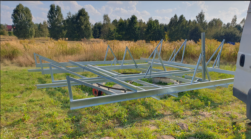
Each REI solar tracker has been designed so that everyone is able to assemble and run the device. What's more, you can make a work surface for 12, 15 or 18 photovoltaic panels up to 1.7 m high. This means that in today's conditions you can safely get up to 9kWp power on one tracker, receiving evev 14MWh per year. From one tracker only! This is much more than household expectations and is prfect form agriculture The set (without work surface) can arrive on a EUR pallet. The work surface itself can be made entirely of steel metallurgy available in stocks without welding.
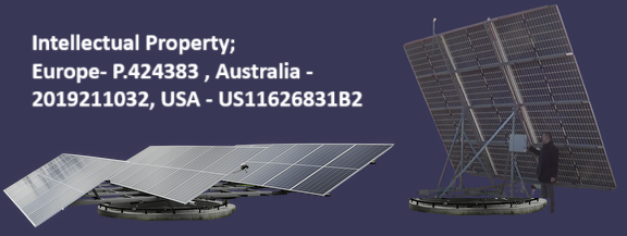
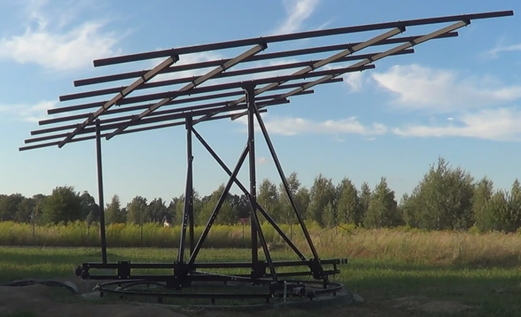
REI "BooM" solar tracker is higher [5,5m] and thanks to this it can stand e.g. in an orchard, in a bushy area and in the vicinity of not too tall trees. Such a tracker is ideal for single installations or in a small group. The distance between trackers must be no less than 8 - 12m depending on the terrain. Such trackers are not suitable for a farm. [We have a different product line farm dedicated].
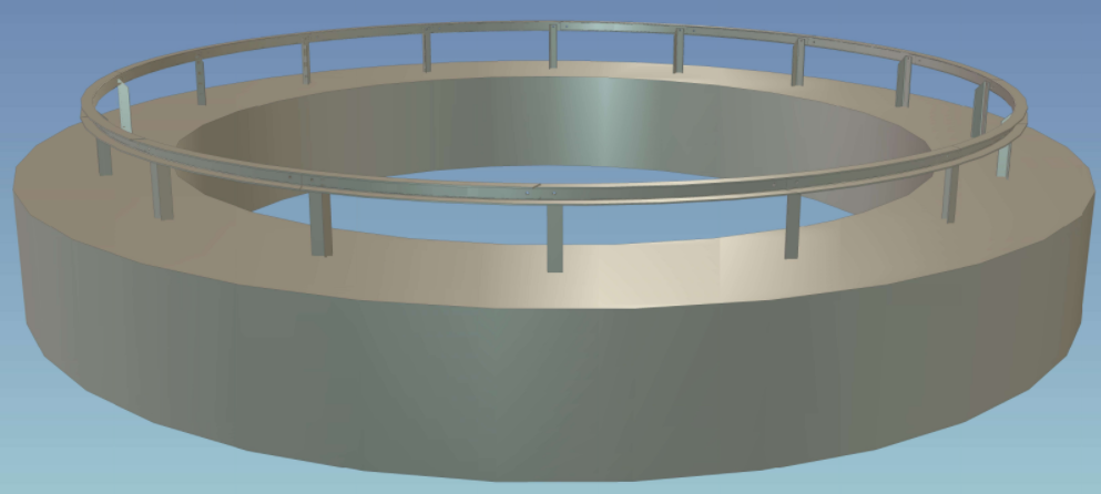
The base is the same form both products and requires pouring the ring, which can be placed directly on the ground (without excavation) or using the ground as a formwork. The height of the ring is about 35-40 cm. Both "wet" and "dry" concrete can be used for pouring such a base. only 1m3 of concrete is needed. No special reinforcement is required, 2 wires ø6 mm are enough to connect the legs in the concrete. (pass through the holes in the legs).
Some also place the structure on posts, sometimes it makes sense when the ground is extremely steep. The structure itself is balanced with the panels so that the profile only provides the stability of the base and no additional weight is required on the base. Spread footing.
You don't have to buy the whole set. If you have a workshop with basic equipment, an angle grinder or a drill and a few wrenches are enough, you can get system elements from us and the drawings and bill of materials needed to make the remaining elements. This way you will save a lot on the entire installation. The work surface and the panels themselves are very easy to install. The working surface consists of profiles up to 6m long, so you pay mainly for transport, not the product itself.
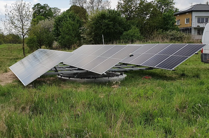
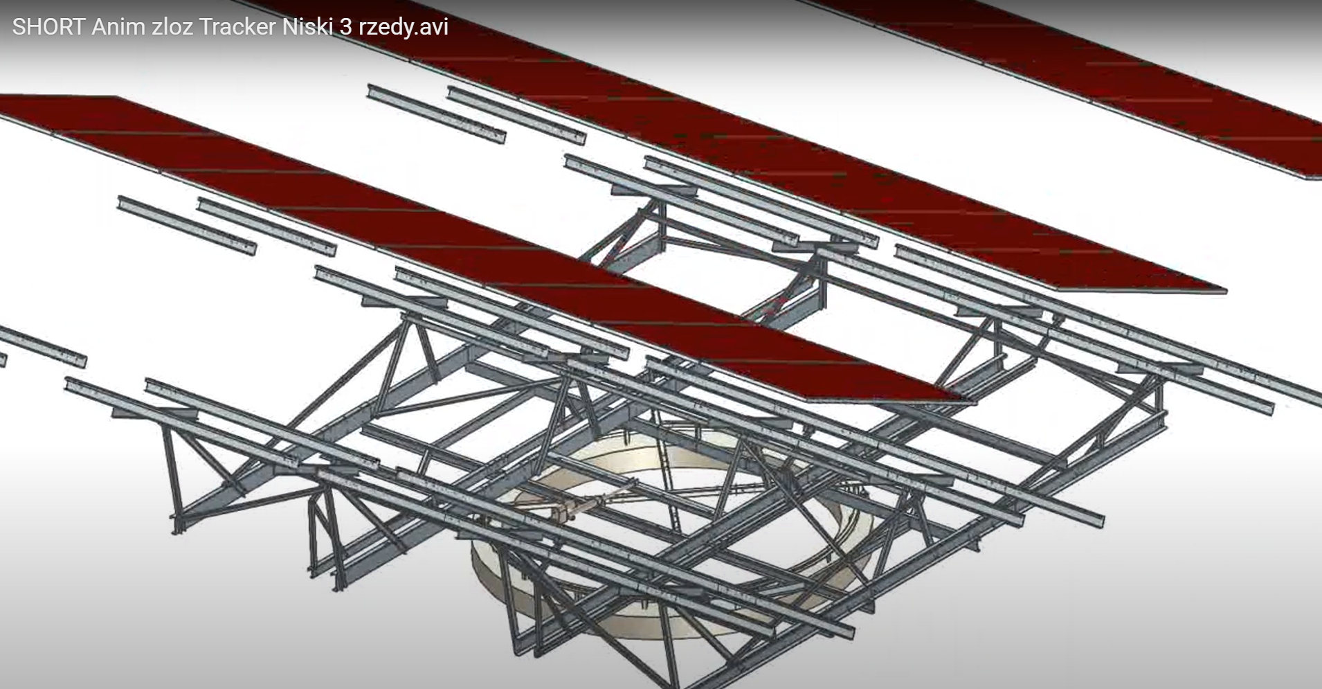
Rei solar tracker "EveN" is a tracker that is maximally lowered. Ideal for farm installations where the length of the shadow has a direct impact on the power density per hectare. Much more resistant to adverse weather conditions. Often installed on trailers as a mobile solution. It is also possible to place the tracker on a flat roof, which works great in the case of dense development.
excluding transport costs Differs much.
Opti kit - basically everything that can be prepared without photovoltaic panels. The rack of the structure requires adjustment to the dimensions of the panels. As you know, the panels have different sizes.
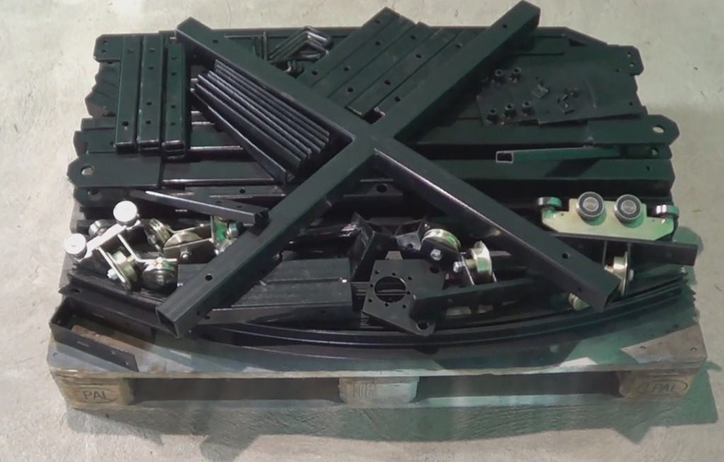
Regardless of the version, we can prepare a set. Pack the construction elements on a pallet and send them. We are looking for partners, contractors, subcontractors in all markets.
Full version - requires the dimensions of the panels to be able to leave the structure well. This has an impact on the balance so that the whole thing works lightly. CAUTION. Here, the price also results from logistics costs. The elements of the working surface are up to 6m long.
Smart Solar Tracker is designed to maintain angle in a horizontal and vertical position of mounted on it device/collector. In our case the Smart Tracker was used for appropriate alignment of tilt, pan, roll angles of photovoltaic panels corresponding to geographical location in relation to the changing position of the sun, in a way, so that sun rays fall on modules fixed on the panel, at an optimal angle to reach the possibly longest time period of maximal power production over every day in the year.
This solution greatly improves efficiency of photovoltaic modules. Measurements taken at an altitude of 51 °N, indicate that energetic efficiency of photovoltaic panels fixed on our rack, over the whole year, increased by 40% in comparison to modules with the same power, fixed on a roof surface in a standard way with direction of 0 °S and tilted at a 35° angle.
Such increment of efficiency allows to greatly limit cost of investments and save space that is necessary to achieve assumed efficiency of the whole installation. Introducing an inexpensive and easy in maintenance and repair design is a condition to achieve this goal.
In the current market there are solutions which allow to modify the position of photovoltaic panels in one or two planes. However, available constructions are designed to handle too small number of panels on a single rack, to make the purchase of such system to be economically reasonable. The reason of limiting the size of the panel surface is inability to expose as-is design to unfavorable atmospheric conditions, e.g. wind force. Suggested rack designs, e.g. of a column type, absorb essential amount of produced energy to position the panels, especially when we deal with the influence of air masses.
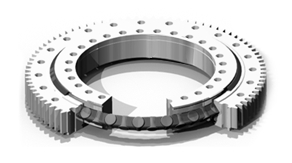
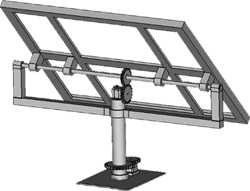
So far, producers use centrally positioned column, in order to apply central mounting of a bearing what results in a lack of possibility to use a drive mechanism other than the one based on a toothed rim. Column based solutions cause an increase of rack production and raise the cost of the whole system.
Some devices that may be found in the market, allow for installation of the larger number of modules, however, they are costly in production because of an expensive method of bearing mounting and an expensive drive for the column structure. Large non-modular elements, force the need for special type of transport and specialised tools and competences for installation. That results in inadequate design-related costs. Such approach of create an extensive farms which have relatively poor return rate of the investment.
Central column alternative
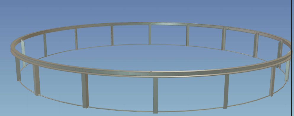
Because economically optimal diameter of the system should be equal to a minimum of 1.5m in radius, the Smart Tracker guide has to have a modular structure, which allows to achieve this assumption without logistic constraints which appear in solid elements. Relatively large diameter of the guide in relation to the height of the rack allowed to acquire three very important and unavailable for other designs, features:
Increased stiffness of the design and frame based structure also enabled to eliminate a weak point of the construction which resulted from imperfections of market available drives designed to tilt the working plane. Engineers commonly use linear motors based on a trapezoidal screw. With mounting as shown on the exemplary figure;

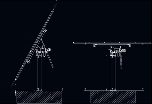
Because the mounting of the linear actuator on a pole structure has to be done in a way that enables the movement of the mounting together with the upper frame, the size of the actuator and its parameters must be significantly limited. The weakness of this solution manifests with a low resistance to a jerk of waving plane working on the wind. The wavy motions are a result of combination of dynamic force of the wind and gravity. The size of the working plane increases the torque that is transferred by the constructions to the linear actuator.
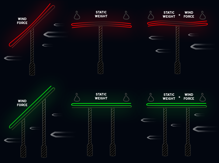
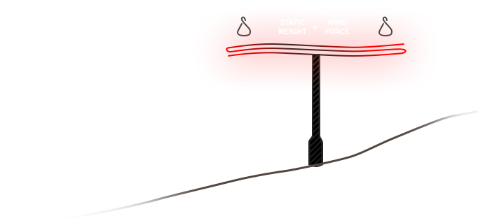
Usage of the dedicated slide drive enables to acquire a beneficial stiffness of the structure, and in addition, in the moment of adjusting working plane to the horizontal secure position (similar to the parallel position towards the earth), it greatly increases the resistance of the system on influence of strong and gusty winds. Most of the controllers available in the market, after connecting a wind gauge, enable to set the rack in a default and safe position in case of detection of threshold speed of the wind. Default position in actual working conditions is not always optimal because of the terrain shape.
Our dedicated slide drive also plays a reinforcing role for the main frame, because its guide is integrated with the elements of the whole framing by skeletal structure.